
Testing Using a Probe

A test interface cable connects the device-under-test (DUT) to the tester. On one end, the wires are terminated with the connector that mates to the tester while the other end is terminated with the connector that mates to DUT.
Like the DUT, interface cables must be tested for errors. The test requirements for interface cables follow the same test process as any cable or harness assembly, but with more stringent test parameters applied to connection resistance, dielectric withstanding voltage, and insulation resistance. Cirris can build interface cables and test them using these standards. Contact your sales representative to learn more.
Testing the interface cables present a challenge when the DUT connector is an exotic connector that is difficult to source, requires a minimum order, has long lead times, or is unreasonably expensive. The DUT may also be pad on a PC board that doesn’t have a mate or a bare wire.
The Cirris Custom Products Group developed a method of meeting the test requirements that does not require the mating connector for the DUT end of the interface cable. This method can also apply to single-ended cables where the wires from the connector are flying leads that will be terminated later.
Test Probe
All Cirris testers are equipped with a test probe. When the probe is connected to the tester and makes electrical contact with a test point, the tester displays the name of the test point the probe is touching.
The Custom Products Team found a way to measure and record resistance using a probe. Testing using a probe would offer many benefits:
- The DUT connector is not required to complete tests.
- The probe declares a test failure when it encounters resistance in excess of the specification.
- The probe provides the actual resistance value in test reports.
Rather than redesign the test probe circuitry, the Custom Products Group found a way to use a standard test point to act as the probe. Using the Easy-Wire’s Sequential Build test method, the process of probing, measuring, and reporting can be managed in a single operation.
The probed point measurement can be tested in both 2W and 4W configurations.
NOTE: This type of testing can be completed on any Cirris tester using Easy-Wire.
Sequential Build
An Easy-Wire test program is a series of test instructions that describe a conductor’s test point origin and test point destination. A valid test program will contain instructions for every interconnection expected to exist in the device-under-test.
When the test method is set to Sequential Build, Easy-Wire requires completion of each instruction in sequence beginning with the first instruction.
Setup Example
Perhaps you are required to test a two-meter long cable assembly with MIL-W-16878/5 EE compliable conductors. Cirris Standard ACCH-DH (plugs into the CH2 connector) terminate the tester end and the mil standard D38999/20WB99PN terminate the DUT end. Other specs include:
- Connection resistance is 0.5 ohms max.
- DWV at 1000 VAC for 1 second with Leakage Current at 2.5 mA max.
- Insulation Resistance 500 M ohms min.
Begin by starting Easy-Wire and choosing Create Test.

Choose to create a test program using traditional fixturing.

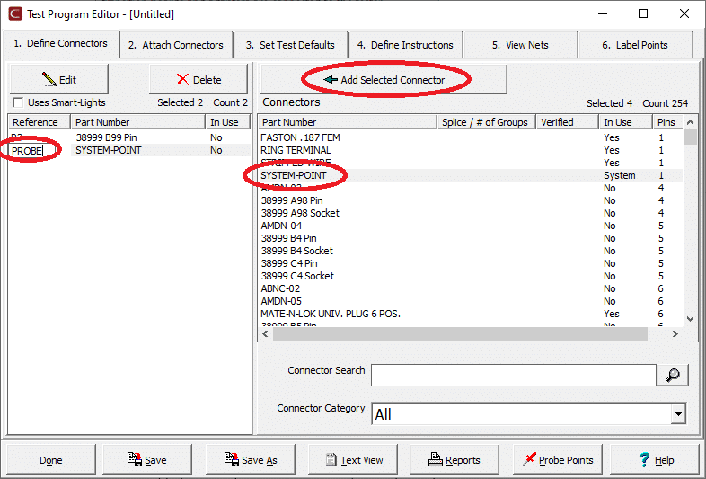
Add the Mil-Spec connector and name it P3.

Next, add any single pin connector and named it Probe.
The customer’s schematic for the interface cable is shown below:

Plug the assembly into the CH2 tester and attached the connector to comply with the customer’s schematic.
The test program contains a fabricated probe lead from a CH2 mating connector with the probe lead connected to the 32nd position of that connector. Plug this assembly into the fifth scanner card of the CH2 so that the fabricated probe occupies system point 160. Then in Easy-Wire, attach the test point named PROBE to the tester at point 160.
This section of the Test Program Report shows the complete attachment arrangement:

Operating Parameters
Under the Set Test Defaults tab, set the Start Condition to Start Button is Pressed.
Set the Test Method to Sequential Build Test.
Check the box next to Show Current Instruction.

Click Set High Voltage.

With the test parameters and test process set, move on to Tab 4 Define Instructions to build a list of Close/Open instructions for the test program.

Why use the Close/Open instructions?
In this scenario, when the Close instruction is executed, Easy-Wire expects a connection of less than 0.5 ohms between the From point, the probe, and the To point—which is a terminal in the DUT mating connector. When the Close instruction is complete, the Open instruction lets Easy-Wire know that the From and To points are not networked for the high voltage testing. Without the Open instruction, the high voltage test treats all points in common with the Probe, and the wire-to-wire test would not be evaluated.
Executing the Test
When the test program is executed, the operator will receive the prompt:

Easy-Wire will pause while awaiting the Probe to contact terminal P3-A with a resistance of less than 0.5 oms. When the Probe is removed from P3-A, the Open instruction is complete, prompting the next Close instruction to execute.
If the Close instruction fails to complete, then either an open circuit or a high resistance circuit has been detected and the operator must Abort. If the Open instruction fails to complete then a short circuit has been detected and again, the operator must Abort.
When all instructions have successfully executed, the high voltage test will proceed.
Special Notes
- If you identify wires by color or another marking, the operator will be required to verify the marking. You can make use of the instruction label on each instruction to identify the correct marking. However, this technique is prone to user-error since the operator is declaring its acceptability,
- This particular test is a single pass test and is not sensitive to intermittent open circuits.
- If the probed points of the DUT happen to be flying leads, consider building the assembly twice as long as required, terminating both ends, and testing. When the assembly passes, cut it in half.