Digital I/O Part 2: Implementation by Tester
Each Cirris Tester implements Digital I/O differently. Follow the instructions below to add Digital I/O to your test system.
8100
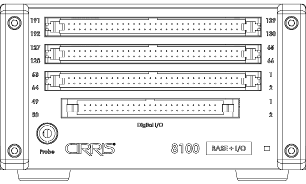
When the Digital I/O option is installed on an 8100 tester, the I/O connector replaces the bottom test points connector on the system Base leaving space for 192 test points instead of the typical 256 points. The 50-position I/O header connector provides 8 pins that can be used as outputs and 20 additional pins that can be used as either inputs or outputs.

Outputs
Outputs are NPN “sinking outputs” meaning that when turned on, an output completes a circuit by connecting it to ground. The output signal does not provide power. The power is provided by the “sourcing” input. It’s recommended to sink no more than 500 mA at one time across all the outputs and to always use multiple ground pins on the I/O connector.
Inputs
VDC logic is typically used to control an input, however, any DC voltage up to a nominal 24 volts may be used. The input is triggered when the input voltage is > 2 volts. The input is off (not triggered) when the input voltage is < 0.8 volts.
I/O Connector Pin-Out

| Pin | Function |
|---|---|
| 1 | N/C |
| 2 | GND |
| 3 | GND |
| 4 | GND |
| 5 | N/C |
| 6 | GND |
| 7 | GND |
| 8 | GND |
| 9 | I/O 0 |
| 10 | I/O 1 |
| 11 | I/O 2 |
| 12 | I/O 3 |
| 13 | I/O 4 |
| 14 | I/O 5 |
| 15 | I/O 6 |
| 16 | I/O 7 |
| 17 | I/O 8 |
| Pin | Function |
|---|---|
| 18 | I/O 9 |
| 19 | I/O 10 |
| 20 | I/O 11 |
| 21 | I/O 12 |
| 22 | I/O 13 |
| 23 | I/O 14 |
| 24 | I/O 15 |
| 25 | I/O 16 |
| 26 | I/O 17 |
| 27 | I/O 18 |
| 28 | I/O 19 |
| 29 | Output 20 |
| 30 | Output 21 |
| 31 | Output 22 |
| 32 | Output 23 |
| 33 | Output 24 |
| 34 | Output 25 |
| Pin | Function |
|---|---|
| 35 | Output 26 |
| 36 | Output 27 |
| 37 | GND |
| 38 | GND |
| 39 | GND |
| 40 | GND |
| 41 | GND |
| 42 | GND |
| 43 | GND |
| 44 | GND |
| 45 | GND |
| 46 | GND |
| 47 | GND |
| 48 | GND |
| 49 | GND |
| 50 | GND |
CH2
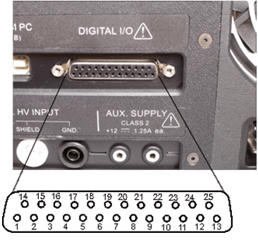
The CH2 tester has built-in Digital I/O capability through a Digital I/O port on the back of each tester. The Digital I/O port can accommodate up to ten inputs that respond to a logic high signal between 5 and 30 VDC (approximate 1.5 V logic threshold). Additionally, ten open collector outputs are capable of sinking up to 500 milliamps and 15 VDC. The Digital I/O connector also supplies +5V and +12V at 140 milliamps each. The diagram and tables below show the CH2 Digital I/O port pin out and pin assignments.

| Inputs | Pin |
|---|---|
| 0 | 23 |
| 1 | 19 |
| 2 | 7 |
| 3 | 20 |
| 4 | 8 |
| 5 | 21 |
| 6 | 9 |
| 7 | 22 |
| 8 | 10 |
| 9 | 11 |
| Outputs | Pin |
|---|---|
| 0 | 1 |
| 1 | 14 |
| 2 | 2 |
| 3 | 15 |
| 4 | 3 |
| 5 | 16 |
| 6 | 4 |
| 7 | 17 |
| 8 | 5 |
| 9 | 18 |
| Other | Pin |
|---|---|
| +5 VDC | 12 |
| +12 VDC | 13 |
| Ground | 25 |
| HV INterlock | 6 |
Note: CH2 testers built after April 2008 require a connection on the Digital I/O port between pin 6 and pin 25 in order to output high voltage. CH2 testers with this capability are factory equipped with an HV Interlock Override which makes a default connection between these two pins. You can however wire an HV Interlock to these pins to help ensure the operator does not come into contact with high voltage. You can use the HV Interlock Override connector and connector housing to make other Digital I/O connection(s) to the CH2 tester.
Easy-Touch Pro
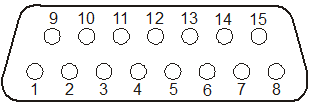
The digital I/O port is located on the back of the tester. The location and pinout of the connector are as shown. The table below explains each of the signals on the IO port. Note there is one “External Switch” input, six user-programmable outputs, two power pins and two ground pins.

| Pin | Explanation |
|---|---|
| 1 | Input 0 External Switch |
| 2 | Input 1 Hipot Switch |
| 3 | Input 2 |
| 4 | Input 3 |
| 5 | Output 0 |
| 6 | Output 1 |
| 7 | Output 4 |
| 8 | Output 5 |
| 9 | Power + 5 VDC, 100 mA max. |
| 10 | Output 2 |
| 11 | Output 3 |
| 12 | Power + 10 VDC, 100 mA max. |
| 13 | Not used |
| 14 | Ground |
| 15 | Ground |
Inputs
The digital I/O port for these testers has four inputs. VDC logic is typically used to control an input; however, any VDC up to a nominal 24 volts may be used. The input is triggered when the input voltage is > 2 volts. The input is off (not triggered) when the input voltage is < 0.8 volts.
Outputs
The outputs on the digital I/O port are “sink” outputs. When activated they will connect (or sink) the output to ground. The outputs are capable of sinking up to 500 mA at 24 VDC. To limit the output current, always ensure adequate resistance between power supply and the output. When switching a voltage between 12 and 24 volts, the output will allow a slight current flow (about 1mA at 24 volts) when the output is OFF. You can set up test events to turn an output ON (sink) or OFF (float).
See the User Manual and Help System for setup instructions.
CR
To enable the CR tester for use of digital I/O capability, purchase the upgraded easy-wire software which includes the Virtual I/O Package (part # SIO-EW). You will also need to purchase a Direct Logic DL05 Micro PLC from Direct Logic (Click Here for a link to the Direct Logic web page).

