

Digital I/O Part 4: Examples
The following are instructions of how to use Digital I/O to improve your test process.
- External Switch
- Hipot Safety Switch
- Outputs
- Controlling an LED to indicate hipot
- Turning on a Light Bulb
- Momentarily activating an air valve
External Switch
You can use any input. However if you were to select input 0, the external switch circuit, would look like the following:
Easy-Touch®
|
CH2Note the interlock or interlock override circuit (between pins 6 and 25) is not shown on this schematic, but must be present to start the high voltage test on the CH2.
|
CR
|
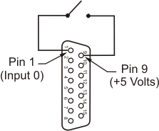

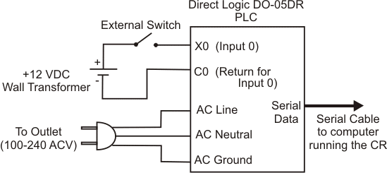
Note as shown above, the Easy-Touch and CH2 can supply +5 volts on their IO connector to provide a logic high to the input pin. When using the CR you use a wall transformer or another voltage source to provide 12 to 24 volt for the PLC input.
Completing the External Switch in the Test Setup:
- When setting up the test, under the Set Test Defaults Tab in the Test Editor, click the Configure Inputs and Outputs button.
- (Optional) Use the Edit I/O Names Button to name your IO input. In the example schematic above, we use we would name input 0 something like External Start Switch.
- Under the Available I/O Instructions click the appropriate tab PLC I/O or Built In I/O.
- Under the I/O Instruction Blocks Highlight the SetButtonOnInput instruction.
- Under I/O Instruction blocks, click on the Initialize tab.
- Click the Add New Instruction button. Set Button when Input is High, Select Input is INPUT 0, and Button is TEST. Then click OK. This will cause the start button to be pressed when in the Test Window.
- If desired, you can also allow the operater to start the test with the RETEST button. Add a SetButtonOnInput instruction under the GoodTest tab so when INPUT 0 is high RETEST is pressed.
- Click OK to exit the button window and Done to exit the Edit I/O Blocks window.
- Select a Start Condition that will start the test when the start button is pressed. On the Easy-Touch tester select Signature Single Test Mode to allow the test to start when the start button is pressed.
Hipot Safety Switch
You can start the hipot test by closing an external hipot safety switch. The safety switch might be dual palm switches wired in series, a foot pedal, or a sensor in automated test equipment. Note that the CH2 has HV Interlock connections on the IO connector, which can be used to start the Hipot test. The CH2 will not start or continue the high voltage test unless the interlock connection is present. If you use an interlock switch with the CH2, you would typically not need a separate hipot safety switch.
To use an Hipot Safety Switch with the Easy-Touch, you need to first have the Digital I/O and Windows Messaging Windows option enabled using the easy-wire Feature Registration Utility. Then select an input on the Easy-Touch digital I/O connector. Wire the hipot safety switch or switches as in the Easy-Touch schematic above for the External Switch.
To Complete the Hipot Safety Switch
- When setting up the test, under the Set Test Defaults Tab in the Test Editor, click the Configure Inputs and Outputs button.
- (Optional) Use the Edit I/O Names Button to name your IO input. In the example schematic above, we use we would name input 0 something like Hipot Start Palm Switch.
- Under the Available I/O Instructions click Built In I/O.
- Under the I/O Instruction Blocks Highlight the SetButtonOnInput instruction.
- Under I/O Instruction blocks, click on the Start Test tab.
- Click the Add New Instruction button. Set Button when Input is High, Select Input is INPUT 0 or it’s new name, and Button is HIPOT. Then click OK. This will allow the HIPOT button to be pressed when the hipot test is ready to start.
- Under HVTestStarted Tab add a SetButtonOnInput instruction so that a low state on the hipot safety input triggers the ABORT hipot button. This will ensure the operator presses down on the hipot safety switch throughout the test.
- Under both the HVTestPassed and the HVTestFailed Tabs add a SetButtonOnInput instruction so that a high state on the hipot safety input triggers Button None. This will allow the test window return to it’s intended display even when the operator is continuing to depress the hipot safety switch(s).
- Click Done to exit the Edit I/O Blocks window.
Outputs
The CH2 and Easy-Touch testers have “sink” outputs. When activated they will connect (or sink) a voltage to ground, in effect turning ON the output circuit. The Easy-Touch outputs are capable of sinking up to a nominal 24 volts and 500 milliamps. The CH2 outputs are limited to sinking 15 volts and 500 milliamps. To limit the output current, always ensure adequate resistance between power supply and the output.
Current cannot flow when the normal state of each output is off. One test event sinks the output to ground, thereby allowing current flow through the output circuit. You must remember to program a second event to reset the output its original OFF state.
To sink an Easy-Touch output, you will specify an IO instruction to set the output low; to unsink the output, you will specify another instruction to set the output high. On the CH2 and CR testers, you turn on the output by specifying a high, and turn off the output by specifying a low. Remember, once turned on an output will remain on until another IO instructions to turns it off. Attempt to think through and test every scenario to ensure an output will always be at a know state.
For step-by-step examples on setting up Digital Outputs, see the output examples below.
Controlling a LED to indicate hipot
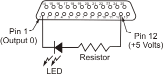
Let’s say you want to light an LED to warn the operator before the hipot test starts and during the test. The brightness of an LED is proportional to the current that passes through it. Most LED’s have a maximum current rating of 20 milliamps (mA). In this example, the LED requires 20 mA. On the CH2 and Easy-Touch testers we can use the +5 DC volt supply on the digital I/O port to power our circuit, but will need a resistor to limit the current flow to 20 mA.
How do you choose the resistor? From the LED spec sheet we find the LED in this instance has a forward bias voltage drop of two volts; therefore when using the 5 Volt supply, 3 will drop across the current limiting resistor. Knowing voltage drop and current through the circuit, Ohms Law can be used to determine the resistor value.
Therefore for the 5VDC supply,
The power though the resistor will equal the current through the circuit (0.020 amps) multiplied by the voltage drop across the resistor (3 volts) gives us a power dissipation across the resistor of .06 watts. We therefore know we can use a tenth watt resistor to dissipate the power.
In the case of the CH2 and Easy-Touch testers, when the hipot test is ready to start and during the hipot test, these tester will pull the output to ground allowing current to flow in the circuit, and the LED will turn on. When the hipot test completes, current through the output will stop, and the LED will turn off.
Easy-Touch
|
CH2
|

To complete the hipot LED setup
- When setting up the test, under the Set Test Defaults Tab in the Test Editor, click the Configure Inputs and Outputs button.
- (Optional) Use the Edit I/O Names Button to name your IO output. In the example schematic above, we use we would name output 0 something like Hipot LED.
- Under the Available I/O Instructions click Built In I/O (Easy-Touch and CH2) or PLC I/O (CR).
- Under the I/O Instruction Blocks Highlight the SetOutput instruction.
- Under I/O Instruction blocks, click on the LVTestPassed tab.
- Click the Add New Instruction button. In this example for the Easy-Touch tester, you would set Output 0 (or its named value) to be low. For the CH2 you would set Output 0 to high*. This will sink the output, allow current flow, and thereby cause the hipot LED to illuminate when the high voltage test is ready to start.
- Under the HVTestPassed and the HVTestFailed Buttons add Set Output 0 (in this example) to be High for the Easy-Touch tester, or Low for the CH2 tester. This will turn off (unsink) the output after the hipot test has stopped.
- Click Done to exit the Edit I/O Blocks window.
* Selecting High on the CH2 or CR tester signifies that the output is ON or sinking low. Selecting Low on the CH2 or CR tester signifies the output is OFF or high.
Turning on a Light Bulb
Let’s say instead of an LED, you want to turn on a light bulb powered from a 120 VAC wall outlet. The light bulb will illuminate each time there is bad test. For the Easy-Touch and CH2 a relay can be used to control the light bulb. In this example, we select a relay that has a coil voltage of 12 volts and draws less than 100 milliamps so we can use the +12 volt DC power supply on the the Easy-Touch and CH2 testers. For the CR tester the AC light bulb can wire directly to the PLC. The light bulb circuit for each of the testers is as shown.
Easy-Touch
|
CH2
|
CR
|
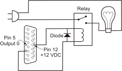
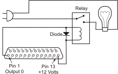

Note, it’s important that you add a diode, such as a 1N4002, across the relay to protect the digital I/O port from the reverse current created from the coil when the output turns off.
To complete the light bulb setup
- When setting up the test, under the Set Test Defaults Tab in the Test Editor, click the Configure Inputs and Outputs button.
- (Optional) Use the Edit I/O Names Button to name your IO output. In the example schematic above, we use we would name output 0 something like “Bad Test Light”.
- Under the Available I/O Instructions click Built In I/O (Easy-Touch and CH2) or PLC I/O (CR).
- Under the I/O Instruction Blocks Highlight the SetOutput instruction.
- Under I/O Instruction blocks, arrow over to and click the BadTest tab.
- Click the Add New Instruction button. In this example, you would set the output state of Output 0 (or its named value) to be Low for the Easy-Touch tester or High for the CH2 and CR*. This will sink the output, allow current flow and thereby activate the relay to illuminate the light when there is a bad test.
- Under the Initialize and StartTest tabs, add Set Output 0 (in this example) to be High for the Easy-Touch tester, or Low for the CH2 and CR tester. This will turn off (unsink) the output after the hipot test has stopped.
- Click Done to exit the Edit I/O Blocks window.
* Selecting High on the CH2 or CR tester signifies that the output is ON or sinking low. Selecting Low on the CH2 or CR tester signifies the output is OFF or high.
Momentarily Activating an an Air Valve
Let’s say you want to control an air valve for equipment that will automatically stamp “tested good” on each assembly that passes a test. In this example, the air valve will need a 30-millisecond pulse to activate. We’ll also say that the solenoid for the air piston requires DC 24 volts and 300 milliamps (the coil resistance is 80 ohms).
Note: The digital I/O port on the Easy-Touch and CH2 cannot supply 24 volts or the required 300 milliamps for the air valve. In this case, you need to use an external power supply for the valve circuit. The output on the Easy-Touch sink up to 24 DC volts and 500 milliamps. The CH2 can sink up to 15 DC volts, we can therefore use a relay with a 12 volt DC coil to drive the 24 volt solenoid. The valve circuit for each of the tester types is shown below.
Easy-Touch
|
CH2
|
CR
|
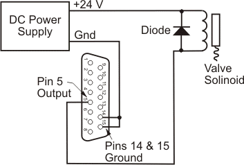

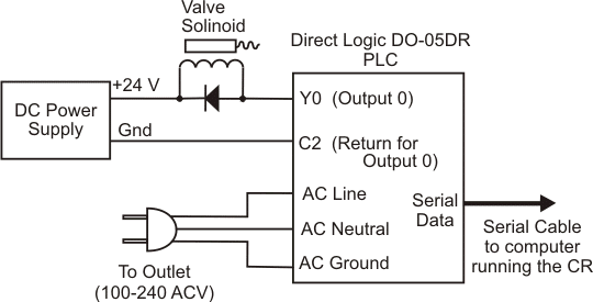
In this example, a diode such as a 1N4002, is added across the relay to and valve solenoids to protect the outputs and alleviate voltage spikes in the circuits.
To complete the setup in software
- When setting up the test, under the Set Test Defaults Tab in the Test Editor, click the Configure Inputs and Outputs button.
- (Optional) Use the Edit I/O Names Button to name your IO output. In the example schematic above, we use we would name output 0 something like “Stamp Good Valve”.
- Under the Available I/O Instructions click Built In I/O (Easy-Touch and CH2) or PLC I/O (CR).
- Under the I/O Instruction Blocks Highlight the SetOutput instruction.
- Under I/O Instruction blocks, arrow over to and click the WillCountGood tab.
- Click the Add New Instruction button. In this example, you would set the output state of Output 0 (or its named value) to Low for the Easy-Touch, or to High* for the CH2 and CR. This will sink the output, allow current flow, and thereby activate the valve or valve relay. Also enter a delay setting of 20 milliseconds. This will establish a pulse period sufficient to activate the stamping action.
- Again under the WillCountGood tab, click the Add New Instruction button. Set the output state to High for the Easy-Touch, or Low* for the CH2 and CR. This instruction will unsink the output to end the 20 millisecond pulse from the previous instruction.
- Click Done to exit the Edit I/O Blocks window.
* Selecting High on the CH2 or CR tester signifies that the output is ON or sinking low. Selecting Low on the CH2 or CR tester signifies the output is OFF or high.
Go to: