

Easy-Wire® Features: First-Ended Pinning and Open/Close Instructions
The wire-harness industry’s most capable testing software is chock-full of useful features to make testing as convenient and reliable as possible. Cirris Easy-Wire™ Software helps make sure cables and harnesses are thoroughly tested. While many of the features in Easy-Wire are well-known and used for nearly every test, others are less familiar to users. Read about some of the useful features found in Easy-Wire Software.
First-End Pinning
Please note that first end pinning is only available on the Cirris CR tester model.
See our article on Guided First-End Pinning in the Cirris Learning Center to learn more about the purpose of first-end pinning.
Testing First-End Pinning
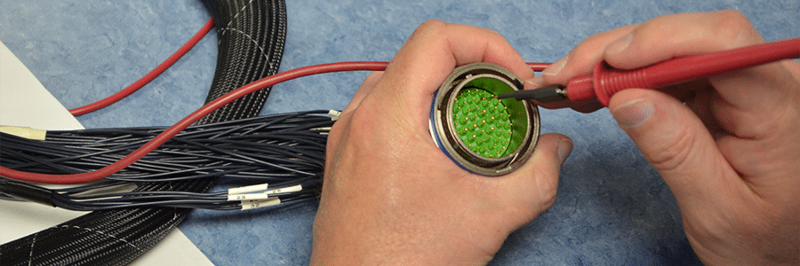
The tester uses capacitance to sense when a wire’s pin has been inserted.
There are two ways to do first end pinning using Easy-Wire software.
The first is to use the test method, Sequential Build Test. In this mode the tester prompts for a defined sequence of wires so the assembly person does not need to enter the wire label.
The second way is to “tell” the tester which labeled wire you are going to insert. There are two ways to do this.
First, use Random Build mode and scan a bar code which identifies the wire. The tester then displays a graphic of the connector with the target cavity for the specific wire clearly highlighted.
The other method of “telling” the tester is by using the “Install Pin” instruction used with the Random Build Test mode. When the test is started, the “Install Pin” instruction will require the test operator to manually enter a wire label. When the wire label is entered, Easy-Wire will display the pin position for the wire identified by the label.
Open/Close Instructions
Use Open and Close instructions when creating test programs in Easy-Wire to ensure test operators have a chance to test situations like the following:
Suppose your product has two networks defined as J1-A to P1-A and a separate network that is J1-B to P1-B. These two networks would be tested for shorts to each other during low voltage isolation testing. If a hipot test is programmed, the networks would be tested against the other with each being brought to high potential individually while the other is held to ground.
If you have a switch connecting J1-A to J1-B, you will want to test the switch in both the open and closed positions. When the OPEN instruction is executed, the tester treats these as separate networks. When the CLOSED instruction is executed, you expect continuity through the switch and J1-A to P1-A to J1-B to P1-B is treated as a single network.
Since the high voltage test is the final process in the complete test process, the final state of the OPEN and CLOSE instruction is how the tester manages the net during hipot.

In the example above, the high voltage test will consider J1-A to P1-A to J1-B to P1-B as a single net.

In this example, the high voltage test will consider J1-A to P1-A as a net and J1-B to P1-B as a separate net.
Momentary Switch
If the final state of the OPEN/CLOSE instruction is OPEN—to check for shorts and isolation across the switch—the problem arises when the switch is momentary.
A “momentary” switch changes state as long as it’s being pushed or held. As soon as it’s released, it goes back to its default state.
In the above example, the default (normal) state is closed (meaning it makes the connection in its default state). The final state of the OPEN/CLOSE instruction is what the shorts test and the HV test expects. The operator would have to hold the switch during the HV test if the last state of the test program was OPEN.
For safety, an external appliance is needed to maintain switch actuation during the HV test.