

Impedance and Resistance
Sometimes the terms “impedance” and “resistance” are used interchangeably, even by those who are familiar with the shocking ways of electronics. Well, why not? They are both calculated the same way using the formula R=V/I and they are both expressed in units of ohms.
The terms are not as synonymous as you might believe. Think about it this way, do you think that a short run of RJ series coaxial cable really has 75 ohms from one end to the other? Then how is it that that coax is still 75 ohms, no matter the length?
Because your Cirris test results may depend on the definitions of resistance and impedance, let’s draw some distinctions between these two terms.
| Resistance | Impedance |
|---|---|
| A property of a circuit that opposes direct current. | A property of a circuit that opposes alternating current. The amount of opposition, or impedance, is proportional to the frequency of the alternations of current. |
| Power is dissipated as heat. | Power is transformed and stored in electromagnetic fields. |
Since one of the biggest differences between resistance and impedance comes down to current, let’s see how this looks in terms of testing.
Testing on DC vs AC
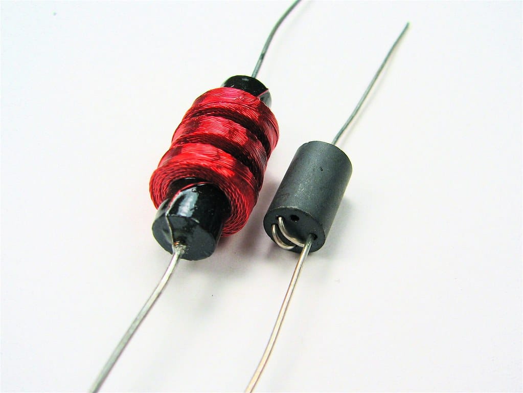
“Two inductors”by oskay is licensed under CC BY 2.0![]()
![]()
Cirris testers are DC when testing continuity. However, at the beginning of each test, the test current changes from zero to some other value. While we want to express the quality of a connection in terms of connection resistance which fits with the DC design, we expect the reactive devices—such as inductors (coils) and capacitance—to just get over the sudden change in state we present to the circuit that looks like AC to them.
In an alternating current circuit, capacitors and inductors become reactive and then resist the transfer of power.
- A capacitor is an open circuit to DC but conducts in the presence of AC.
- An inductor will resist the changes in current. Each device will react differently to different frequencies.
Most of the capacitors and inductors are small enough for Cirris testers to accommodate their little fits of reactance.
It’s All a Matter of Time
When we measure the connection resistance of a circuit and report its value, we are applying a current source to one end of the circuit and sinking the other end to zero potential. Then, almost immediately, we measure the voltage across the circuit. We take this information and perform Ohm’s law arithmetic—divide the voltage by the current to learn the resistance of the circuit.
When reactive components are between source and sink, their reaction will cause the voltage across the circuit to rise slowly or diminish slowly as the current is applied. The result, in terms of resistance, is variable because we have collected the voltage measurement while it was moving up or down.
What to do?
First, understand that you are not measuring impedance on your Cirris tester. Even though the voltage is changing, as long as the tester is using DC it is measuring the resistance and not the impedance. There are several ways you can adjuster your tester and process to ensure resistance does not hinder test results.
Give your tester more time
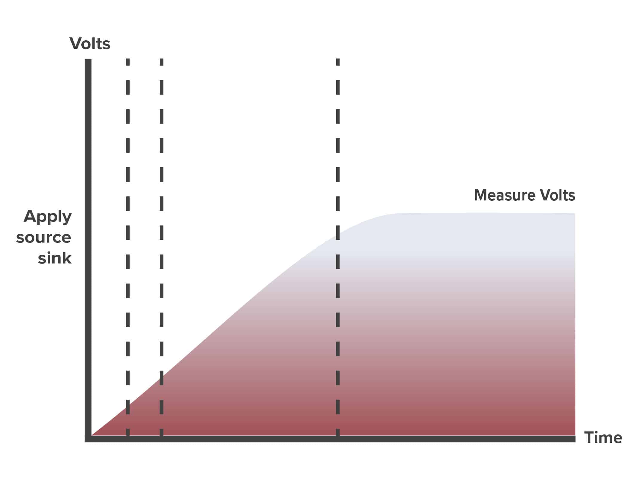
In Easy-Wire, there is an instruction called “DelayResis.” This instruction allows a little more time for the circuit to settle before the tester measures the voltage.
The graph shows the response of an inductive load. Note the voltage at the time the tester makes the voltage measurement. Since the inductive load has not “settled” the value will vary each time the circuit is measured because the time between sourcing/sinking and measuring is set.
In the test program, you could express the connection resistance as a nominal resistor value with a tolerance wide enough to accommodate the variation in voltage—just the variation in the time between sourcing, sinking, and measuring the voltage drop.
Be consistent
The speed of your Cirris tester is nearly the same among comparable models within the industry. When a known good part behaves a certain way on a Cirris tester, it should behave the same way on another tester. There are things that can affect the speed between two similar tester models.
- Make sure the connection resistance and the low voltage insulation resistance is set the same.
- A low voltage insulation resistance of about 100K Ohms will provide the fastest shorts test.
- Place reactive component measurements at the top of the instruction list.
Ignore reactive components
Set the low voltage insulation resistance just below the lowest value the reactive component returns. The tester considers all connections with values greater than this setting to be open. Make sure the connection is not in your instruction list; otherwise, the instruction will return an open circuit test result. If the reactor is short to another circuit the tester will catch it. If the reactor is short to itself (not an uncommon condition in coils) the tester will catch this too.
Measure the Capacitance
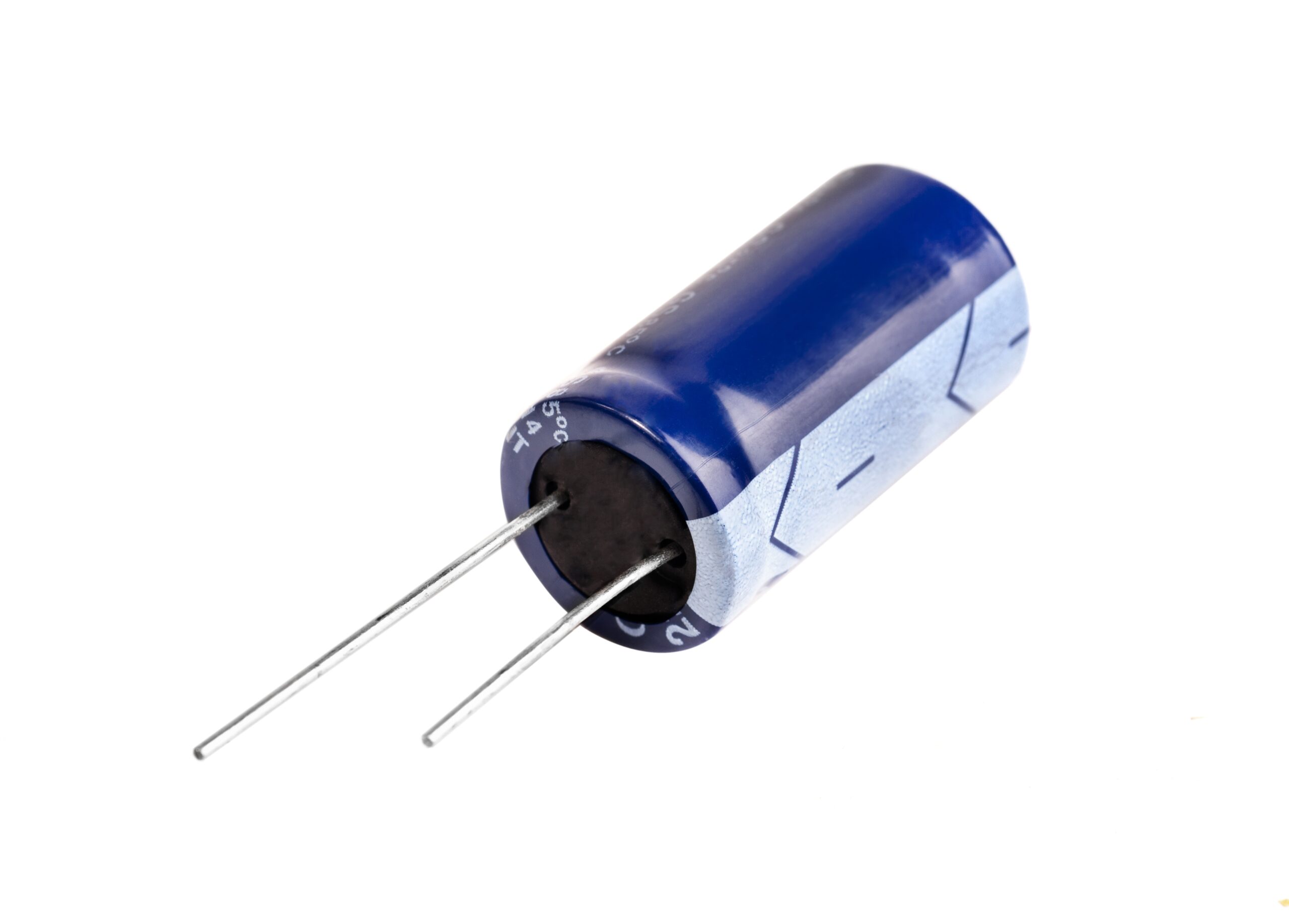
Capacitors are measured with what’s available—a current source, a timer, a voltage source, and a microprocessor.
Cirris testers do not have oscillating signals to measure capacitors. Capacitors are measured with what’s available—a current source, a timer, a voltage source, and a microprocessor.
The formula: Q=CV describes how the charge (Q), capacitance (C), and voltage (V) interact. When the voltage is zero, the charge will be zero (if V=0, then Q=0). If you double the voltage (V), you will double the charge (Q).
Sometimes it is useful to think in terms of current (I). The relationship between current, voltage, and capacitance is I = C(dV/dt). This says that the current (I) in a capacitor (C) is proportional to the rate of change of voltage (dV/dt) across the capacitor.
Applying some algebra, we can also state that C = I/(dV/dt). Capacitance is equal to the current divided by the quantity of the change in volts divided by the change in time.
With this equation in mind, here is how the Cirris tester measures capacitors:
- Voltage across the cap is forced to -1 volt.
- A current source is applied to one side of the cap and the other side sinks to zero volts.
- A timer starts the moment step 2 begins.
- The voltage across the cap is measured and monitored.
- When the voltage across the cap equals zero, the timer stops, and the time is recorded.
The value obtained in step 5 is the change in voltage (dV)—which we know is 1 volt—and the change in time (dt). Since we already know the current, we now have all the values needed to determine capacitance with the formula C= I/(dV/dt).
Keep in mind that the returned capacitance value includes the effects of other components that are parallel to the target component.
Measure Inductors and Capacitors with External LCR Meter
The Cirris model CH2 has a unique design that allows the use of external instruments such as the Precision LCR Meter. Under the direction of Easy-Wire custom component, the CH2 test points will direct the LCR meter’s probes to the target component in your device-under-test.
The Precision LCR Meter directed by Easy-Wire can make and report on complex impedance evaluations. Set the test and acceptance parameters in Easy-Wire and the LCR meter makes the measurements. Offsets are available to accommodate parasitic effects of your interface.
Many native functions of the LCR meter such as dissipation factor, phase, and magnitude are available as custom components in Easy-Wire.