

Connector Contact Retention
A key problem with wire harness assemblies constructed with crimp and poke style terminations is contact retention failures or terminal “push back.” Of primary concern are those instances when a contact is sufficiently inserted to pass initial visual inspection and standard continuity testing, but which isn’t fully seated. This condition prevents the contact’s locking mechanism from fully engaging and sets the stage for subsequent contact push-back failures which can result in:
- Electrical Open circuits
- High Resistance Connections
- Intermittent Connections
Four Methods to Confirm Contact Retention
1. Operator Training: Push-Click-Pull Method
The IPC/WHMA A-620 Standard, section 19.7.5, reads in part: ..the ‘push-click-pull’ method of pushing a contact into the insert until the retaining mechanism clicks and then pulling on the attached lead until it is taut shall be used…
Advantages:
- Easy, no tools required
- Complies with IPC/WHMA A-620 Standard (for all classes when using crimp and insert style contacts unless other test requirements are specified)
- No fixtures required
Disadvantages
- No clear specification on Pull forces
- Prone to Human error
Related Links:
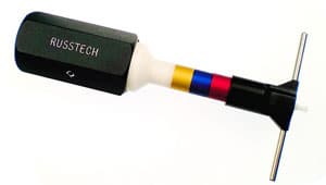
2. Contact Retention Hand Tools
Several contact retention hand tools are available for performing push-back tests one contact at a time from the face of the connector. Certain specs require this type of contact retention test (NASA)
Advantages:
- Clear specification
- Compliance requirement for NASA
- No fixture required
Disadvantages:
- Cost in labor time to check
- Discovery of errors after assembly completed
- Test one-contact-at-a-time after assembly
Related Links:
3. Electrical Test with Spring Probes for Pushback
(Requires Fixture that moves probes into contact with connector contacts, then backs away)
Electrical test fixtures that use heavy pressure spring-loaded pogo pins can be used, but care must be taken to use a 2-stage fixture that fully engages the pogo pins, then backs them off slightly before the electrical test is performed. Otherwise, the electrical test may still pass because pushed back pins may still be in contact with the spring probes.
Advantages:
- Clear specification for retention from pin side of the connector
Disadvantages:
- Requires test fixtures for every connector
- Insertion force increases with pin count (3 lbs x # of contacts)
- Requires mechanical levers or pneumatically operated fixtures
- Requires 2-stage pneumatic fixture to ‘contact then back off’ (lower cost spring probes but more expensive test fixture)
- Difficult to keep probes accurately positioned
Related Links:
4. Electrical Test with Switch Probes for Pushback
(Requires costlier switch probes instead of standard spring probes)
Electrical test fixtures that use heavy pressure switch probes don’t require the 2-stage fixture described above. Current flows in the switch probe only when the plunger is depressed enough to close the switch, so a pushed back pin will fail electrical tests with an open circuit.
Advantages:
- Clear specification for retention from pin side of the connector
- Simplifies fixture engagement design. (Probe pins do not need to be backed off)
Disadvantages:
- Requires test fixture for every connector.
- Insertion force increases with pin count. (3 lbs x # of contacts) Requires mechanical levers or pneumatically operated fixtures
- Switch probes are much higher cost than standard spring probes.
- Difficult to keep probes accurately positioned.
Related Links:
Changes to Connector Design – Prevent Retention Issues
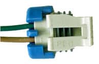
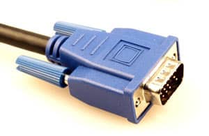
1. Push-to-Seat Terminals with TPA:
A push-to-seat terminal is a terminal that is inserted into the back of the connector cavity until it locks in place. Terminal Position Assurance (TPA) devices are plastic inserts that keep these contacts in place after their insertion in the connector body. A TPA clip is the blue part in the photo on the left. These designs are 100% effective in eliminating the chance of pushback. However, using this design requires inspection for the presence of the TPA and also requires choosing a connector design that uses TPA styling. Often used by the automotive industry.

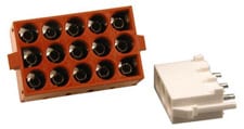
2. Pull-to-Seat Terminals
Pull-to-seat Terminals (requiring crimping after the wire is inserted through connector body). This design is 100% effective in eliminating the chance of pushback because the terminal cannot be pushed out through the back of the connector. The biggest challenges are with labor and equipment cost because termination occurs after inserting the wire through the correct position of the connector body. If there is a miswire or broken contact in the manufacturing process, it requires cutting off the termination/contact to repair. Very time-consuming!

3. Potting and Over-molding
Advantages:
- Reasonably effective in preventing push-back
Disadvantages:
- Does not ensure it is fully inserted at the time of potting/over molding (pin height problem)
- Increased cost and labor
- Prevents or hinders failure analysis and rework
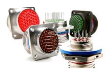
Examples of Crimped-Pin Contact Retention Methods
1. Friction or Interference Lock
The contacts fit very snugly into a hard rubber insert. Contacts are installed and removed by force using the proper tooling. The contacts are usually inserted from the rear of the connector and removed from the front (face) of the connector.

2. Contact Lock
The locking device is located on the contact itself in the form of a spring finger which snaps into place on a ring inside the insert. The contacts are usually inserted from the rear of the connector and removed from the front (face) of the connector.
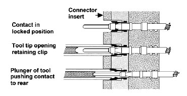
3. Insert Lock
The contact has a ridge (shoulder) machined around the contact, which snaps into place in the spring clips (tines) that are located inside each cavity of the insert. The contacts are usually inserted from the rear of the connector and removed either from the front or rear of the connector.
The top contact, in the ‘insert lock’ illustrations (left), is shown in the “locked” position. The middle contact is shown with the tool probe or tip opening the spring clips. The bottom contact is shown as it moves out of the rear of the connector.

For more complete information on this topic follow this link to a PDF authored by CMS (Connector Microtooling Systems)