

High Voltage Testing on Small Pitch Connectors
As the spacing between contacts in connectors on small pitch connectors gets smaller, there comes a point where cables will not pass at higher voltages. This becomes a problem when certain specifications such as IPC/WHMA A-620 requires voltages as high as 1000V or 1500V. What do you do if your cable has connectors that won’t pass this requirement?
If you make changes to the high voltage test because of failures due to spacing issues, you will need to be able to explain these adjustments and the reason you cannot test at the specified voltages.
Creepage Distance/Air Gap, The Path of Least Resistance
Electricity likes to travel along the path of least resistance. Looking for the best path for electricity usually means measuring the distance from one conductor to another conductor. The shortest distance may be through air (air gap) or along the surface of the insulation (creepage distance).
Connectors are the most likely place in a cable assembly where this “path of least resistance” exists, especially on small pitch connectors. This path is across, not through, insulation and is measured in either “air gap” or “creepage distance.” Electricity can arc either in the air between two pins or along the insulating surface between two conductors.
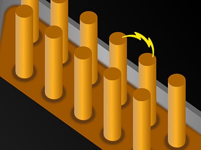
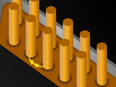
along an insulator is called ‘creepage’.
How Much Voltage to De-rate?
First, you must determine the minimum creepage or air gap distance. We have created an article to help you to do this. You can find it here.
Once you know the creepage or air gap distance, you need to figure out a reasonable amount to de-rate the test voltage. Cirris has created an arc gap calculator which can be found on our website.
Note: Creepage/air gap calculations are relevant not only to the assembly you are testing, but also to any interface cabling/test fixtures that you use to connect to the device under test.
Using the information from our Arc Gap Calculator page, we built a table of voltages and their potential arc distance. Since variations can occur in applied voltages and manufactured dimensions for creepage in connectors, we created a .002″ + 10% protection factor into the Arc Gap dimensions.
| Measured Creepage in inches | Measured Creepage in mm | Maximun Test Voltage* |
|---|---|---|
| <0.004 | <0.11 | 300 |
| 0.004 | 0.11 | 500 |
| 0.005 | 0.13 | 600 |
| 0.006 | 0.16 | 800 |
| 0.009 | 0.22 | 1000 |
| 0.010 | 0.25 | 1100 |
| 0.013 | 0.33 | 1200 |
| 0.016 | 0.41 | 1300 |
| 0.019 | 0.47 | 1400 |
| 0.023 | 0.58 | 1500 |
| 0.027 | 0.69 | 1600 |
| 0.033 | 0.83 | 1700 |
| 0.038 | 0.97 | 1800 |
| 0.042 | 1.06 | 1900 |
| 0.047 | 1.20 | 2000 |
| * DC or Peak RMS AC voltage | ||
Variation to A-620
Considerations for A-620 Class 3 (High Performance Electronic Products)
For Class 3, use 1500VDC as specified when creepage distance is at least .58mm (.027″). For smaller creepage distances, if the design of the product cannot be changed to improve creepage distance, then limit voltage for DWV and IR tests according to the above table.
Considerations for A-620 Class 2 (Dedicated Service Products)
Occasionally someone is confused why A-620 for Class 2 skips the high voltage requirement if there are high enough creepage distances.
The reasoning is that if connectors have large separation between conductors, there is a low risk of shorts between conductors. However, the closer the conductors are, the higher the risk of a defect such as a stray wire strand or deformed contact causing a failure. As connections get closer, there is more likelihood that shorts will occur, requiring more rigorous testing (higher voltage). The smaller the spacing between conductors, the more important it is to do high voltage testing, but only up to a point.
For Class 2 creepage distances from 2mm (.079″) down to .22mm (.009″) use 1000VDC as specified. For smaller creepage distances, if the design of the product cannot be changed to improve creepage distance, then limit voltage for DWV and IR tests according to the above table.
A Word of Caution if You Comply With A-620:
Until A-620 is revised to include issues with creepage distances, remember the language:
“In the absence of specific agreed on test requirements between User and Manufacturer, or an agreement by the User to accept the Manufacturer’s documented test requirements…”
This means that unless the User and Manufacturer come to an agreement, the values listed in A-620 must be used for test purposes.
For Class 1 and 2 assemblies with creepage distance issues, get specific, agreed on test requirements, perhaps using the information on this page to help make your case.
OR
If customers have agreed to use your “documented test requirements,” modify your documented requirements with something like the de-rating described on this page. This might be as simple as adding the following disclaimer:
“If a high voltage test is performed according to the requirements of A-620, test voltages may be limited due to creepage distance. In these situations, the following table will be used:” [insert the table from above]
What if creepage issues only exist for “some” nets?
It is possible to have a cable that has a combination of connectors that DO and DO NOT have creepage issues. Consider, for example, a cable that has a 15 pin high-density D-Sub that contains only 15 wires out of dozens, or hundreds, of wires. In this case we recommend you test the assembly at two different voltages. A lower voltage for all wires connected to the 15 pin micro D, and a higher voltage for all other wires. All Cirris testers that use Easy-Wire™ allow you to choose different voltages for different nets in an assembly.