

How to Determine Creepage Distance for Connectors
Creepage Distance/Air Gap: The Path of Least Resistance
Electricity, like water, likes to travel along the path of least resistance. Looking for the best path for electricity usually means measuring the distance from one conductor to another conductor. The shortest distance may be through air (air gap) or along the surface of the insulation (creepage distance).
The connectors are the most likely place in a cable assembly where this “path of least resistance” exists. This path is above, not through, insulation and is measured in either “air gap” or “creepage distance.” Ask the question: “How far does electricity need to travel between two pins in the air or along the insulating surface between two conductors in order to arc over?”
Check the Pins on the Connector Face
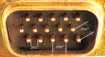
As an example, a 15 pin high-density d-Sub miniature connector has contacts on 0.090″ spacing. The subsequent rows are spaced 0.078″ away and the pins of the three rows are offset from each other by 0.045″. This provides 0.090″ spacing between all diagonal contacts (if they were not equal, we would need to use the smaller dimension). So, what is the creepage distance of this connector?
If you guessed 0.090″, you forgot to subtract the diameter of the pin at the surface of the connector. The size 22 pin has a 0.03″ diameter, so half a pin diameter is subtracted from the distance from center to center of two adjacent pins: 0.090″ – 0.030″/2 – 0.030″/2 = 0.060″
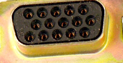
Check the Backside of the Connector:
The real creepage distance may still be less than measured on the connector face. It is likely that the termination end is larger in diameter than the pin at the face. A #22 contact at the termination side can be 0.044″ in diameter. Now our creepage distance is 0.090″ – 0.044″ = 0.046″ (many connectors such as those with crimp-and-poke contacts have insulation from the connector housing on the insertion side that completely covers the backside of the contact. So, in those connectors the creepage path will likely be longer than that on the face of the connector and won’t be the area of shortest creepage).

Check Female Contacts as well:
What about the socket? The end that accepts the pin can be 0.062 in diameter. This would leave 0.090″ – 0.062 = 0.038″ of gap. Usually this is not where the path is shortest. Why? The socket is slightly recessed in the connector housing providing additional distance for this creepage path.
Check For Hidden Creepage Paths Inside the Connector
Sometimes the creepage distance is hidden. D-Sub miniatures are typically manufactured with two plastic insulators, one in front and one in back, which capture the contacts in-between. Let’s see how big the contact shoulder is that holds the contact in place by separating the 2 halves. The shoulder measures 0.073″, so the internal creepage distance is 0.090″ – 0.073″ = 0.017″. According to our arc gap calculator, this dimension could fail at around 1425 VDC.


Check for Hidden Creepage Paths Outside the Connector
Some of the other connector creepage distances can be hidden. If the connector solders to a PCB, inspect adjacent PCB pads for the connector contacts both on the top and bottom of the PCB. Conformal coatings can provide good protection and eliminate the path for breakdowns. Solder mask does not provide an effective barrier against creepage (as you can see in the photo below in which the mask has worn away in spots).

As the brief analysis above illustrates, checking all creepage variables can be time consuming! However, as you diligently explore each of your test failures, you will come to better understand the test challenges that different style connectors present. The design insights gleaned from this practice will enable you to justify lowering test voltage specifications to meet your “real world” test needs. After all, you cannot test cables more stringently than the physics of the cable will allow!
Creepage Checklist:
- Subtract the pin/socket diameters.
- Check the creepage on the backside of the connector.
- Check creepage for the female contact too.
- Look for hidden creepage paths Inside the connector.
- Look for hidden creepage paths Outside the connector.