

Functional Testing
This article should help you understand functional testing, how to apply it correctly, and issues to consider when choosing a tester with functional test capability.
Functional Testing Defined
Harness assemblies can include passive components such as resistors, diodes, and capacitors. Automated harness testers can make measurements on these types of components. However, electrical assemblies can sometimes incorporate active components such as relays, lamps, actuators, and sensors, which require higher current and voltage levels than standard test points can apply.
Harness testers with functional testing capability can verify the functionality of active components by applying the working energization voltage and current to activate the components and to observe their responses. In the case of relays, the expected response is the switching of the relay contact(s), which in turn results in changes to the pattern of connections. The test system can then verify the correct change in connection pattern. In the case of lights and actuators, the test system may prompt the operator to verify the expected response, or the test system can evaluate the change of state using a sensor.


Good Practices in Functional Testing
When testing active components, the best practice is to first verify their presence and correct electrical characteristics, as well as to verify the correct connection pattern of the tested device in an unenergized state. After this first step, the next step is to energize the active component and observe the correct response. This can prevent damage to sensitive components in the device under test, and in some cases, is helpful to ensure the safety of the test operator. Once confirmed, the next step is to energize the active component and to ensure the correct response.
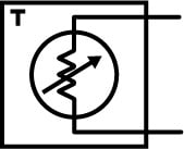
For example, in the simple circuit example at left, the tester would first test the circuit in an unenergized state, testing for the correct relay coil resistance (between A and B), the correct connection resistance between D, E and F, and the absence of shorts to these nets. Once done, you have identified the correct relay is installed and it appears to be initially wired into the circuit correctly. Now as the second step, the tester would energize the relay. In this state, the test system can verify the correct motor winding resistance (between C and F) and verify the absence of shorts. Again, now that the motor characteristics have been verified, the tester can proceed to energize the motor. A sensor or the person running the test could verify the correct motor speed and provide feedback to the test system.
Programming for Complex Relay Circuits
Even programing the functional test for the simple circuit above showed the need to think through a series of steps. On complex circuits the task is much more challenging. The test programmer needs to ensure there will be complete test coverage, making sure that the state of each relay and all possible circuit paths are checked. You will want to make sure you have a schematic of the device-under-test. To make the programming task easier, consider printing a few copies of the relay schematic for each relay state that will be tested. On each copy, use a pencil to edit the relay switch states and use a highlighter to verify that the affected circuit paths are checked.
In rare instances the relays contacts in complex circuits may not be readily accessible. To provide full test coverage in these instances, or to simplify the test program, you may need to make special connections to exposed conductors for the test.
Functional Versus Non-Functional Test Systems
It is important to understand that not all cable and harness testers are designed to support functional testing. Test systems that support functional testing are designed to ensure that the test points can withstand the energization voltage to which they could be inadvertently subjected. Automated harness test systems that support functional testing can apply the energization voltage to active components through the test system in an automated way, without operator intervention.
Choosing the Right Functional Test System
Test Systems that support functional testing vary in the in the levels of voltage and current they can supply to energize active components.
When choosing a functional test system, you also need to evaluate if a single energization voltage, or multiple energization voltages are required for your testing needs. Assemblies that include active devices that all have the same working voltage can be activated by routing the voltage from a single, inexpensive power supply. However, assemblies with active devices that have multiple working voltages require either a programmable power supply or multiple power supplies as the source.
If it is necessary to apply more than one working voltage at the same time, the test system must support multiple energization voltage inputs. Consider the simple circuit above. If the non-latching relay required energization of 24 VDC, and the motor required 125 VAC, the test system would need to support at least two separate energization voltages on its energization bus.
Test systems for large aerospace and rail assemblies allow multiple energization supplies to be located at the base unit of the test system. However, the daisy chain cable from the base to the distributed test point units carries the energization voltage so it is available throughout the distributed test system.
Some test systems support multi-bus points, which can both test and energize. Those that do not must use a separate y-cable to combine test and energization points to DUT points. Using multi-bus points or combining the points in this way allows the system to perform the two-step test and energize process described previously in this topic.
For certain active devices, the test system should be able to interface with sensors, which monitor things like a mechanical movement, the color of emitted light, or a rotational speed. The test system should be capable of providing pictures and prompts so the operator can interact with switches or knobs, allowing the system to verify the states of these components. Moreover, the test system should be able to prompt the operator to observe the change of state of lamps and other components and allow the operator to confirm the observations to the test system. The mobile display at right allows an operator to move through a large assembly like an aircraft fuselage, interacting with active components and responding to prompts from the test system.
After reading this topic you should now understand what functional testing is, how it is applied, and be prepared to choose the right harness tester for your functional testing needs.
Cirris CH2 Tester
Performs functional testing with CH2 Energization Box, which supports one energization supply; Max Energization: 48 VAC volts max, 68 VDC max, 2A Max

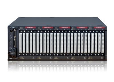
adaptronic NT 800 Test System
Supports functional testing with up to four energization supplies; Max Energization 220 VAC, 310 VDC, 5A; Multi Bus Test Points; Energization available to distributed test points